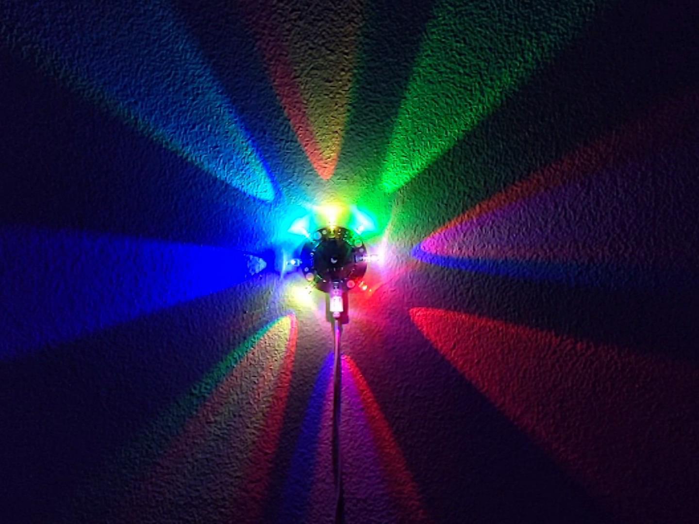
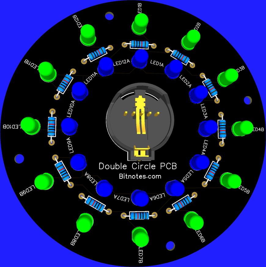
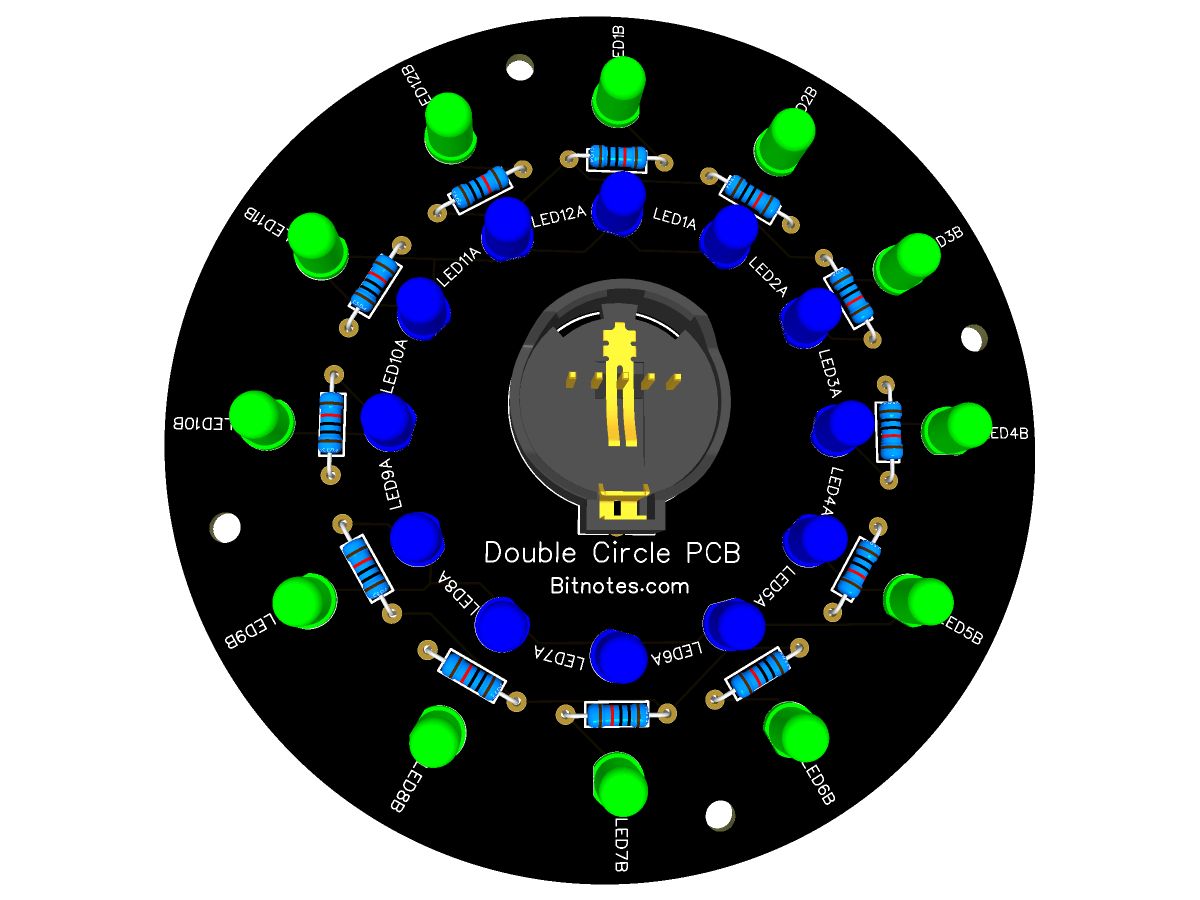
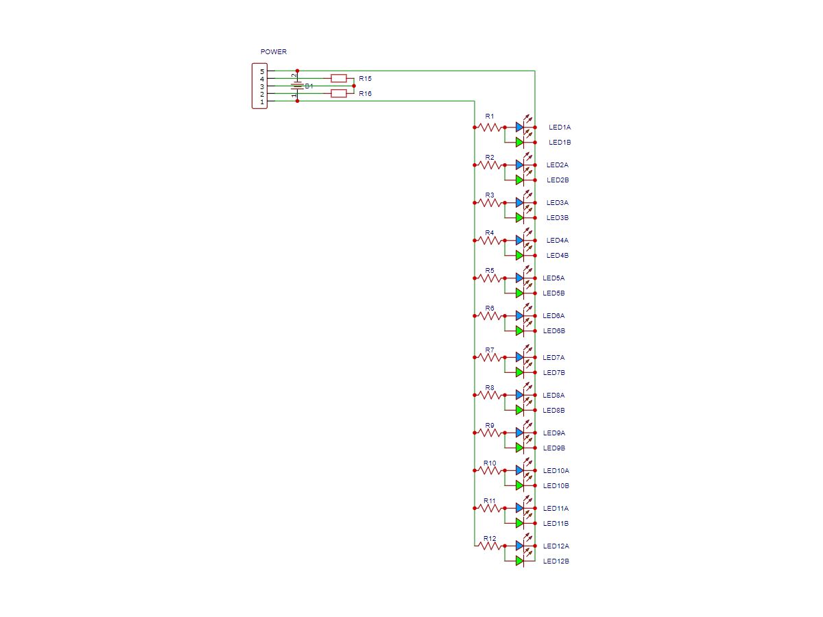
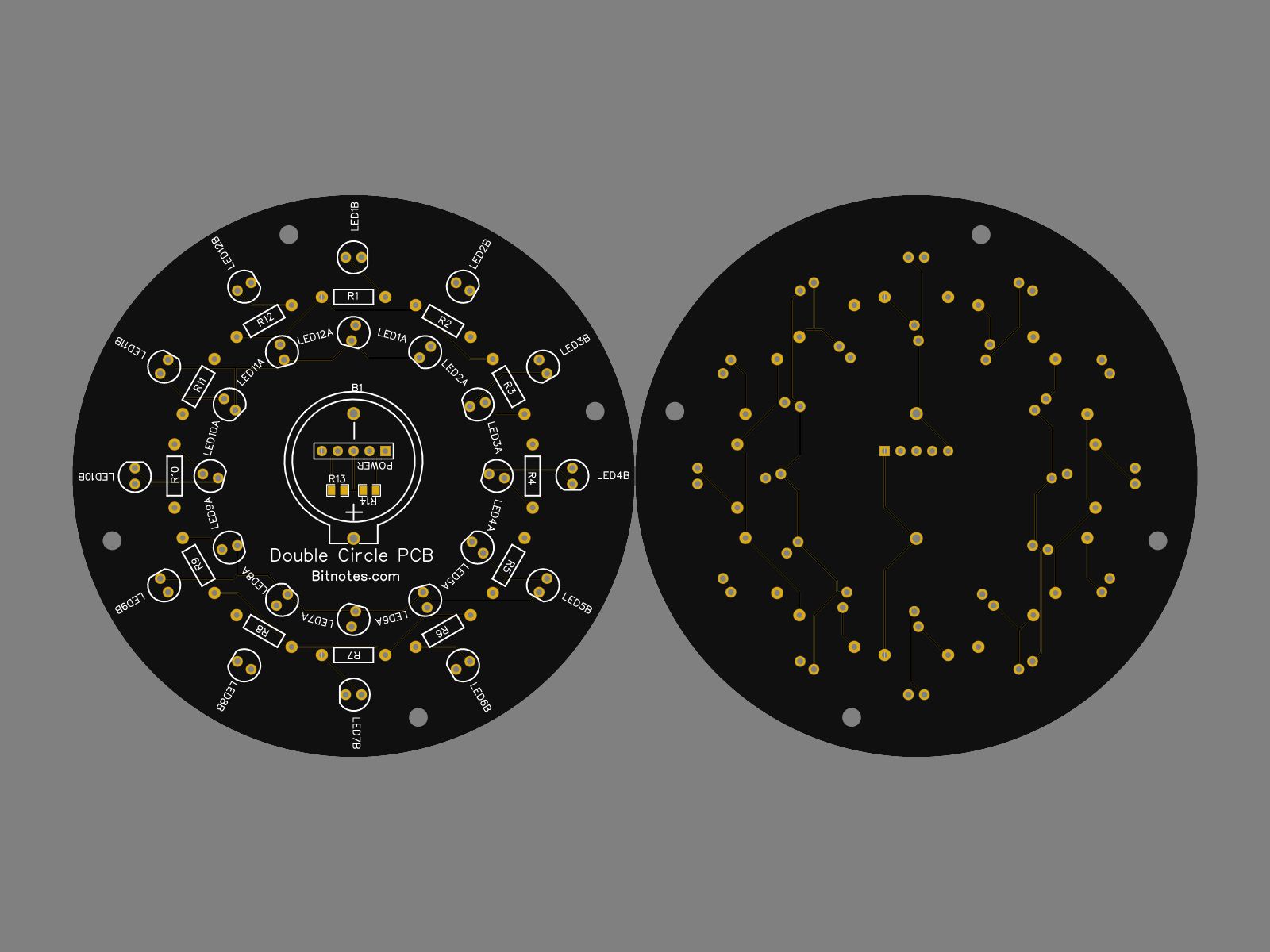
Each POSITION has two LEDs in parallel and 1 resistor. You can use just one or both LEDs and should pick a resistor to set the current.
Pins for each LED in the outer circle are oriented so you can either stand the LED straight up or bend it over to radiate out over the edge of the board.
Pins for each LED in the inner circle are oriented so you can either stand the LED straight up or bend it over to view the LEDs side on leaving very little gap between segments.
Each LED is 30 degrees from each of its neighbors
The diameter of the inner circle is 45.8 mm (A little over 1 3/4 inches)
THe diameter of the outer circle is 70 mm (A hair over 2 3/4 inches)
The PCB has a diameter of 90 mm
Power can be applied in either of three ways:
There is a 5 pin header in the middle that could accomodate a USB breakout board (see kit for example) or just connect at "+" and "-".
There is an outline for a 20xx (i.e. CR2032) button cell holder. Those batteries won't last nearly as long as others, but if you have a very low current draw it might work and there would be no wires running off the board.
You could also use the battery contacts to direct wire to another power source.
There are 4 holes 90 degrees apart. These are all 3 mm and can be used to mount, stack, hang or just hover above a table for a glowing effect..
Related
We have more PCBs and kits. Here are just a few. Click any image below to view that item.
Image above is just one possible configuration. Choice of colors and brightness are up to you.
Board is open source and can be downloaded to make your own. If I have any spares, they will be listed on Ebay the link to which you'll find on the Downlad/Buy/Video page.
You are also allowed to modify this as long as you credit BitNotes.com as the source and Double Circle and the version number (on the download page) as the Model you based your design on.
ELECTRICAL SPECS
Schematic is above
There are 12 sets of 2 LEDs in parallel, each with it's own resistor
Each set of 2 LEDs are also in parallel with each other. Each of those is on either the outer or inner ring. You can configure these any way you need as long as you calculate the necessary resistor to achieve the current draw you want for each LED.
There is one main power connector in the middle (5 pin header for micro-USB breakout board, but + and - are labeled) and an additional provision for a 20 mm button cell holder. The positive an negative connections are in parallel.
Board traces are 0.254 mm wide.
PHYSICAL SPECS
Layout is above (Front on the Left)
Board is 90mm diameter
Four 3mm mounting hole at 90 degrees to each other and 5 mm from the edge of the board.
The 5 pin power connector is 4 mm from the center
LEDs are 22.9 mm and 35 mm from center and 30 degrees apart
Resistors are 28.65 mm from center and also 30 degrees apart
Downloads and Links
You are welcome to download the Gerber file and make your own.
You can even modify the design to fit your own needs and sell these or the resulting PCBs.
However, this is NOT public domain. I am granting you a licese under the terms noted at the bottom of the page. Downloading means you agree to these terms.
In short, if you are selling these or modifying and selling the resulting product, you need to credit me and specify the version as well as linking back to BitNotes.com.
How to order your own:
Go to your preferred board manufacturer like JLCPCB or PCBWay or whatever works for you.
When you see the opportunity to upload a Gerber file, upload the file you can download below
In many cases you can select from multiple colors of "Solder Mask". I chose black just so the board would be so obvious in designs.